
Projects
Various Projects That I Have Undertaken Over The Years
Repaired Wing Screws for a Losmandy Camera Bracket
The wing screws on my Losmandy camera bracket, that rides on a dovetail bar attached to my 8 inch Schmidt-Cassegrain telescope, became brittle with age and finally broke apart. Instead of buying new wing screws and trying to machine one of them like the screw that holds the cameras I broke off the rest of the remaining plastic from the 1/4-20 hex cap screws and 3D printed news wings for the screws. The screws were heated with a candle flame and then pressed into the new wings. They should be good for a few more years of service.

FeeCAD Project

Repaired Wing Screws

Camera Bracket With Wing Screws

Camera Bracket With Wing Screws
Olympus Manual Focus Lens Adapter
Here is a 3D printed adapter for my Olympus manual focus lenses. I purchased a used Olympus bayonet plate and designed an adapter, using FreeCad, to hold the plate on one side and a M42x0.75 thread on the other side. The bottom has a 1/4x20 inch threaded brass insert.

Front

Back

Side

Bottom

FreeCad Screen Shot

Adapter With Lens and Camera

Ready to do an Initial Test

Test Image Using the Waxing Gibbous Moon
Neutral Density Filter Holder
Here is a 3D printed neutral density filter holder for my 50mm SVBONY finder scope. The filter holder will be used in connection with my spectroheliograph to reduce the Sun's intensity so that it does not damage the spectroheliograph. The filter holder will fit over the finder scope's dew shield and is held in place by three nylon thumb screws.

Neutral Density Filter Holder

Neutral Density Filter Holder With Filter
Bogen Tripod Leg Lock Lever
Here is a 3D printed leg lock lever for one of the legs on my Bogen photo tripod. The original lever was broken off about 40 years ago, but the shape of the lever was too complicated to easily make with a conventional milling machine so I just lived with it. After receiving my 3D printer and learning the basics of FreeCAD I realized that I could make the part. Here are the results.

Screen Shot of FreeCAD Rendering of the Part

Screen Shot of FreeCAD Rendering of the Part

Completed Leg Lock Lever

Leg Lock Lever Installed on Tripod
M42 Threaded Adapter
Here is a 3D printed adapter that has a M42x1.0mm thread on one end and a M42x0.75mm thread on the other end that allows me to connect a Pentax 28mm wide angle lens to my ZWO ASI178MC camera. It took a number of attempts to get the thread diameters right due to the shrinkage of the plastic.

M42x1.0mm Thread

M42x0.75mm Thread

Adapter in Place Between Lens and Camera (Indicated by the Red Arrow)

Screen Shot of FreeCAD Showing the Adapter Before Printing It
Spectroheliograph
I purchased a 3D printer to build a spectroheliograph, which will allow me to image the Sun in multiple wavelengths. With a few additional parts the spectroheliograph can be converted over to a stellar spectrograph. The spectroheliograph is being built using the Sol'Ex design by Christian Buil Sol'ex Website. The spectroheliograph will be attached to the finder scope on my 127 mm refractor.

3D Printed Parts

Brass Threaded Inserts Pressed in Place With Heat Press

Initial Assembly

Setup for Focusing the Camera Telescope

Fully Assembled Spectroheliograph in the Process of Being Adjusted

Adjustments Completed and Aluminum Tape Added to Block Stray Light From Entering Between the Two Halves of the Body

Spectroheliograph Set Up For Its First Use

First Spectroheliogram (Low Resolution)

First High Resolution Spectroheliogram
Animation of the Process of Scanning the Sun's Hydrogen Alpha Line With the Spectroheliograph to Produce a Spectroheliogram

Tilt Gauge That Allows Faster Alignment With the Mount's Declination Axis

Close-up of the Tilt Gauge
Aperture Stop for 127mm Refractor
Here is a homemade aperture stop that I made for my 127mm refractor so that I could increase the focal ratio to f/9 from f/5.5, which was required in order to use the Daystar Calcium-H filter that I recently purchased. The stop is made from scrap plywood that I had in my shop. I has three nylon thumbscrews that hold it to the lens cell of the telescope. The thumbscrews thread into machine screw to wood screw adapters that I purchased at the local hardware store.

Front

Back
Mounting Bracket for ZWO EAF Focus Motor
I purchased a ZWO EAF focus motor for my Surplus Shed refractor but ZWO does not provide a mounting bracket that fits the curved surface of the GSO focuser on my refractor so I had to make one in my shop. I traced the curvature of the GSO focuser using a contour gauge and transferred that curvature to a piece of one inch thick scrap aluminum plate and then cut it out on my band saw and finished it up using my disk sander and a file. The rest of the bracket was cut from 1/4 inch aluminum plate. The screw holes in the GSO focuser were transferred to the bracket with transfer bunches. I then drilled the holes out on the drill press and threaded any holes that needed to be threaded. I did an initial assembly that is shown in the first two photographs. Finally, I finished up the edges of the bracket with an end mill and counter sunk the screws that hold bracket to the focuser. I had to make a longer tensioning screw, which I turned out on my lathe from brass. The flexible couplers provided by ZWO did not fit the shaft on the GSO focuser so I took the coupler with the largest diameter hole and made a sleeve for it that fit the shaft on the GSO focuser, and I provided holes in the sleeve to allow the set screws to grip the shaft. The fit of the EAF unit using my bracket is very good and everything lines up nice and straight and the EAF unit moves the GSO focuser very smoothly.

Rough Bracket Installed for Initial Testing

Rough Bracket Installed for Initial Testing

Finished Bracket

Finished Bracket
Telescope with EAF Focus Unit
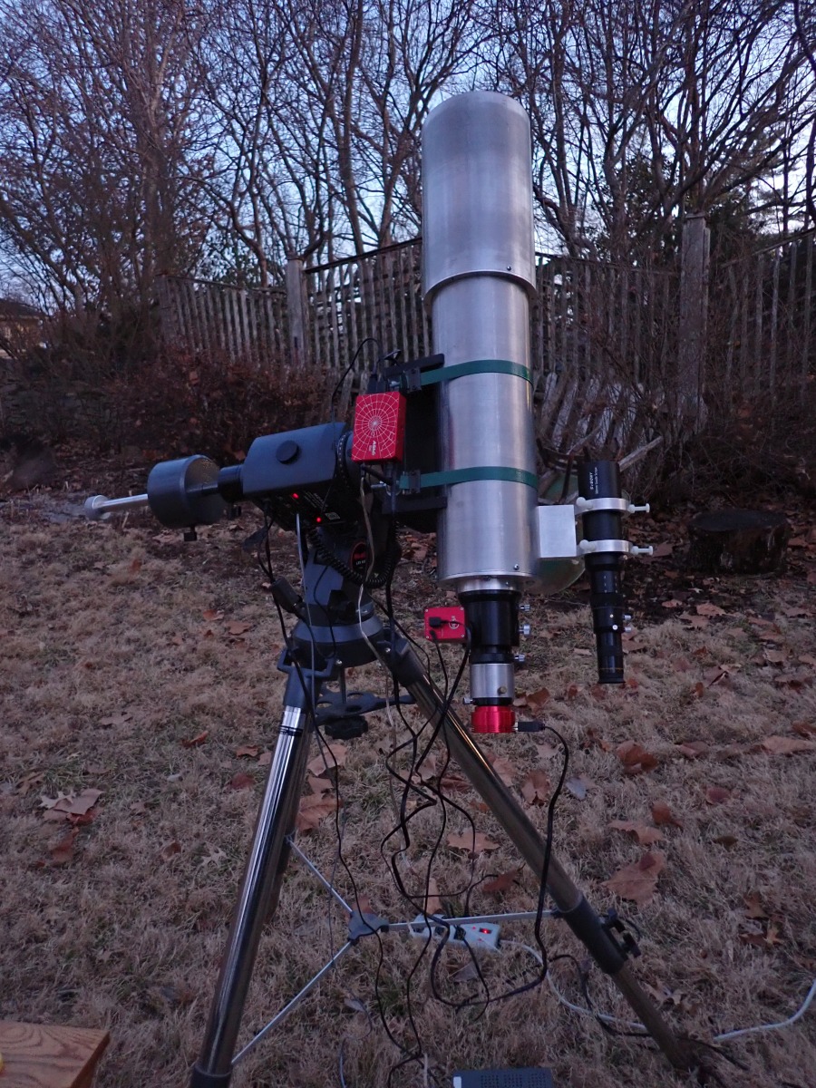
Barn Door Tracker
While taking photographs of Comet NEOWISE C/2020 F3 it occurred to me that the ZWO ASI178 camera that I was using would make a good wide field camera for deep sky work. I found construction plans for a barn door tracker on Gary Seronik's website. Initial trials of the barn door tracker indicated that there was too much flexture in the motor shaft, which has an extension added to it due to the thicker plywood that I used. To overcome the flexture I added a support to the end of the motor shaft that allows me to insert a pin into the hollow end of the extension, which now keeps the small brass gear firmly in place. I also modified the procedure for bending the brass threaded drive rod by forming it with a plastic mallet over a piece of plywood cut out to a 7 inch radius. The following pictures show the completed barn door tracker. For polar alignment I found that opening the upper board while viewing Polaris on live video allows me to determine how good my polar alignment is. If the alignment is good Polaris will follow a small tight arc.
Barn Door Tracker with Praktica Lens
Barn Door Tracker with Praktica Lens
Drive Gears
Curved Threaded Rod
Variable Speed Motor Controller
Power Connector
Small Gear Support
127mm Surplus Shed Refractor
I made this short focal length refractor (700 mm) using a lens from Surplus Shed. The tube assembly was made from solid aluminum disks that were turned on my lathe to hold the lens cell and the focuser and from aluminum tubing. The finder scope was made by Meade, the finder bracket was machined from an aluminum block and bar stock, and the saddle is made from plywood and refrigerator crate straps. The bare bones lens cell provided by Surplus Shed used a lens spacer that was made of plastic that went around the entire outside of the lens, but the spacer was kinked so I replaced it with metal shim material. The other problem with the cell was that the lens elements could not be kept in alignment due to the short focal length of the lens. I modified the cell by installing set screws that allowed me to adjust the two lenses so that their optical axes are properly aligned. I have included a couple of test images of stellar diffraction patterns showing the lens alignment before and after installing the set screws in the lens cell. I machined an outer cell for the lens that allows the optical axis of the lens to be aligned with the axis of the tube. I made an extension tube for the focuser so that I could switch between visual and photographic work.

Objective

2 Inch GSO Focuser and Extension Tube

Side View of OTA

OTA on Meade Mount

Cell

2 Inch GSO Focuser and Meade Finder

Dew Shield

Assembled Refractor

Star Diffraction Pattern Before Installing Set Screws

Star Diffraction Pattern After Installing Set Screws
Heavy Duty Battery Pack
Here is a heavy duty power pack that I made that uses a deep cycle marine battery. It has eight 12 volt power outlets that have fuses. I built the case for the power pack from pine boards that are screwed together. The handle came from an old broom. At a later date I added a 300 watt inverter and a battery level indicator. The sheet metal shield around the inverter was cut from an old computer case cover. I recently made a platform with wheels to help me move the battery pack on hard surfaces. The platform is made from 2x4s and angle iron that I welded together. The wheels are heavy duty casters. The battery pack is very heavy and this wheeled platform makes it a lot easier to move the pack around.

Side View

Top View

Another Top View

300 Watt Inverter

Battery Level Indicator

Wheeled Platform

Wheeled Platform

Wheeled Platform
LXD650 RA Gear Repair
One day I went to use my LXD650 mount and the RA motor would spin but the mount would not slew or track. I opened up the RA gearbox and found that one of the nylon gears was spinning on its pinion. To repair the gear I drilled a #60 hole in the pinion so that I could press fit a small piece of clock pinion wire that would engage slots that I cut into the nylon gear using a jewelers saw and needle files. The nylon gear was pressed over the piece of clock pinion wire, which does a good job of firmly holding the gear without any movement on the pinion shaft. When I pressed the aluminum spur gear back on the pinion it had a small amount of sideways movement on the shaft, which I resolved by putting a drop of super glue on the pinion when I pressed the spur gear in place. The RA gearbox has been performing well since the gear was repaired. The slewing and tracking are good. Considering the age of all of the LX200 classic mounts, which uses the same drive motors as the LXD650 mount, I am certain that others have or will experience similar failures. The tools and materials needed for this repair are a drill press, clock staking set, an assortment of clock pinion wire, a tube of super glue, jewelers saw, small vise, and very small needle files.

Gear pinion
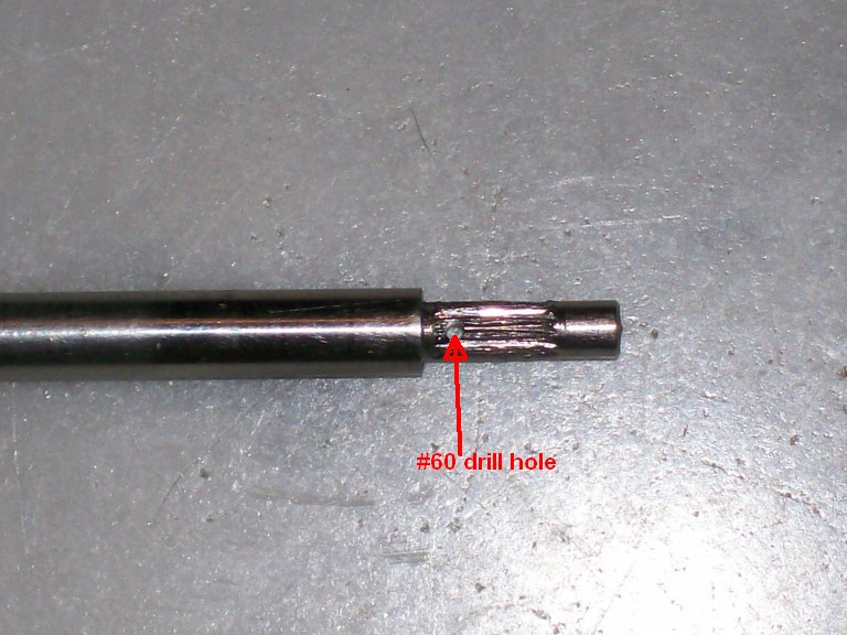
Gear pinion with hole for clock pinion wire

Clock pinion wire pressed through hole in gear pinion
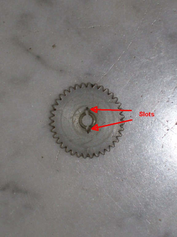
Slots cut into the nylon gear for the clock pinion wire to engage

Nylon gear pressed back onto the pinion with the clock pinion wire engaged with slots cut in the gear

Reassembled gear
Tasco 10TE Refurbishing Project
I received an old Tasco 10TE refractor as a gift that was in bad need of repair. The mount had a lot of paint chipped off from it, along with corrosion where the aluminum was exposed, and there were the remnants of a lot of mud dauber nests all over the telescope. The declination slow motion was broken, The counterweight shaft and counterweight were missing (threads for the shaft in the RA casting were stripped). The RA slow-motion cable was missing. The objective cover and dew shield were missing. The objective had a white residue between the lenses and the brass objective cell was cross-threaded into the steel adjustment ring. The tripod legs had lost a lot of their finish and several of the spacers on the adjustable legs were missing. Most of the chrome was also in bad shape. The repairs started with the objective by removing the retaining ring using a proper optical spanner wrench. It appears that someone in the past tried to remove it with a screwdriver and slipped resulting in a small chip to the surface of the rear lens. I cleaned both lenses (making sure to note the positions of the lines drawn along the edges of the lenses that mark their relative positions) and removed as much of the white residue that was between them that I could. I separated the brass cell from the adjustment ring by grasping the cell from the inside with the jaws of the 4 inch chuck on my lathe and grasped the adjustment ring and gently applied force until the ring came loose from the cell. Fortunately, the threads were not damaged. The finder scope was in just as bad of shape as the rest of the telescope. Its objective lens had been removed from the cell and replaced backwards and the crosshairs were broken off. To repair the broken declination casting I filed down the broken fork so that I had a flat surface and brazed a replacement fork onto the casting that I made from a piece of scrap aluminum plate. To replace the missing cross hair on the finder scope I removed the threaded ring that held the cross hairs and set it on top of an old two liter plastic bottle using double sided tape. New wires were set in place and held under tension with lead weights and then glued in place with 5-minute epoxy.

Objective after cleaning

Declination slow motion mechanism with broken casting

Declination slow motion casting after repair

Rusted declination slow motion cable

Stripped counterweight threads

Tripod legs

Eyepiece tray

Finder cross hair replacement

Finder cross hair test

Draw tube

OTA with draw tube extended

OTA with draw tube retracted
Paint stripped from mount castings

RA slow motion assembly

RA worm and eccentric bushings

RA brass worm gear

Repair of the counter weight thread in the RA casting. The stripped thread was drilled out to 1/2 inch and threaded with a 1/2-20 thread. A steel insert was then made and set into place. The insert is threaded with a 8Mx1.25 thread.

Repaired counter weight thread from the bottom side showing the room left between the steel insert and the RA worm gear bearing surface so that a dirt barrier can be added.

Replacement counterweight shaft that was made from red brass pipe. The endcap on the left has a 8Mx1.25 threaded stainless steel shaft inserted into the end cap. The next step will be to chrome plate the counterweight shaft.

Replacement counterweight. The new counterweight was machined from a piece of 3.5 inch cold rolled steel. I also made the brass locking screw.
Refinished Rattan Chairs
Our four rattan patio chairs were looking very rough (flaking paint and worn out upholstery) so I stripped the chairs down to the bare rattan using lots of paint stripper and lacquer thinner. The residue of the paint and stripper was removed by corn cob blasting the chairs (powdered corn cobs in place of sand with my sand blaster). Each chair was then sanded and then at least three coats of semi-gloss paint were applied with a sanding between each coat. After the paint had set for several weeks the chairs were sent off to be re-upholstered. Two of the chairs had to have the rattan strip, which the upholstery on the backs were stapled to, replaced due to dry rot and splitting. The replacement rattan poles had to be cut lengthwise with a bandsaw then they were steamed and then bent and nailed into place. C-clamps were applied to the new rattan until it were dry.

Rattan chair before stripping

Rattan chair before stripping

Rattan chair before stripping

Rattan chair before stripping

Rattan chairs during stripping and repainting

Finished Chair

Four Finished Chairs
Folding Oak Table
Folding oak laptop table that I made using pictures of a similar table that my brother-in-law has as a pattern.

Folding Oak Table

Folding Oak Table
Adapter Bracket for Meade 616 Filter Wheel
Here is a bracket that I made that allows a Meade 616 filter wheel to be attached to a Meade Pictor 216 CCD camera.

Filter Wheel Bracket

Filter Wheel Bracket
Miter Gauge
Here is a miter gauge that I made for my router table. It is made from 3/8 inch aluminum plate, one inch aluminum bar stock for the T-bar, and one inch aluminum round stock for the knurled handle. The scale was ruled using my indexing table.

Miter Gauge

Miter Gauge Scale

Miter Gauge

Miter Gauge on Router Table
Laser Pointer Bracket
Laser pointer bracket. I made a laser pointer bracket from a couple of platter spacers from an old hard drive, some nylon screws and a piece of 1/4 inch aluminum plate. The laser pointer is mounted on my eight inch Criterion Dynamax telescopes, which I use for public observing. Now when someone asks where the telescope is pointing I just turn on the laser pointer.

Laser Pointer Bracket

Laser pointer and bracket mounted on one of the Criterion Dynamax scopes
Tube Rings
Tube rings for my eight inch rich field Newtonian. About a year and a half ago (July 2010) the mount for my eight inch rich field Newtonian fell over onto my car and then landed on the floor of the garage breaking the saddle that I had made many years ago not to mention leaving a basketball sized dent in my car's front right fender. These rings are made from two layers of 3/4 inch plywood. The plywood layers were glued and screwed together. I used a drum sanding attachment on my drill press to sand the insides of the rings to size and then stained and varnished them. The latch hardware was made using my metal lathe. The notches in the rings where the latch hardware is attached were cut on my router table. On my equipment page you can see the eight inch Newtonian with the old saddle, which consisted of a saddle made from oak with spring steel straps that held the tube in the saddle.

Tube rings

Latch

Hinge

Eight inch Newtonian held by the tube rings
Flat Field Light Box and Carrying Case
This light box was made from 1/4 inch foam core board that was glued together with hot glue. The 3/4 plywood base fits over the end of my Meade 8 inch SCT. There are four 12 volt bulbs inside the box that provide illumination. A sheet of 1/8 inch white plastic acts as the diffuser.

Light box case. Made from 1/4 inch oak plywood and a poplar frame

Light box inside the case with 12 volt power cable

The inside of the case showing Styrofoam lining

The outside of the light box

The light box diffuser

Light bulbs and aluminum shield that directs light upward so that the diffuser is more evenly illuminated
Filter Wheel
Filter wheel for my Watec 120N camera. After using the Watec 120N camera to capture some great deep sky black and white images I decided that I wanted to try using RGB filters with the camera. Since filter wheels can be rather expensive I decided to try my hand at making my own. I cut the filter wheels (two of them just in case I mess up on one of them) from 4 1/2 inch aluminum round stock and faced them off on my lathe. Then I bored a 3/8 inch center hole and turned the outside edge. Next came the holes for the filters using a 1 1/16 inch bimetallic hole saw from the local hardware store. The next step is to use the boring head on my mini-mill to enlarge the holes to 1 1/4 inch.

Filter wheel blank

Cutting the holes

All five holes cut

The boring head enlarging the holes to 1 1/4 inch

Holes bored to size

Threaded inserts cut from eyepiece barrel stock. Note the inserts set into the holes of the filter wheel. I need to find some screws to hold them into place.

The second filter wheel with the holes roughed out by the hole saw

Both filter wheels with the holes bored and inserts temporarily slid into place. Now I need to permanently fix the inserts into place.

Threading the hob which will cut teeth in the filter wheels
Logitech Quick Cam 4000 Adaptor.
I purchased a QC 4000 some time ago but in order to use it I needed a 1.25 inch adaptor to replace the camera's lens assembly. I decided to try my hand at machining one myself. I started with a piece of 1.25 inch aluminum and drilled a hole through it and then turned one end down to fit the camera casing. After getting the camera end roughly turned down to size I bored the inside of the adaptor to size and then finished the camera end so that it made a snug fit into the camera casing. I then painted the inside with flat black enamel spray paint. Finally, the camera was reassembled.

Adaptor - 1.25 Inch Barrel End

Adaptor - Camera End

Finished Adaptor

Adaptor Mounted in QC Casing

Assembled QC - Front View

Assembled QC - Side View
Artificial Star
I decided to build an artificial star to help keep the optics of my Schmidt-Cassegrain collimated in order to improve the quality of my planetary images. Collimating during the valuable moments of good seeing is a waste of good observing so I set out to build the artificial star so that the collimation can be done during the day. I found a couple of Web sites that explain how to build artificial stars. One uses a pin hole in aluminum foil while the other uses optic cable as the point light source.
I went with a fiber optic design since I could keep the light source smaller than a pin hole. A smaller light source can be placed closer to the telescope. A 0.1 mm pin hole has to placed at a distance of 37 meters from an 8 inch telescope, which is too far away for our small back yard. In the article on the fiber optic design the author describes using a 62 micron cable, which still has to be placed at a distance of 23 meters. I decided to go with a smaller diameter fiber (9 micron), which can be placed at a distance of only 3.3 meters. The problem with a small fiber is getting enough light into it so that it is bright enough to be seen. I bought the brightest LED that Radio Shack sells (5000 MCD) and dug up some lenses out of my collection to focus the light of the LED onto one end of the 9 micron fiber that I bought off from eBay. I found an old darkroom enlarger lens that worked nicely as a collimator and another lens with a short focal length (~25 mm) that focused the collimated light onto the fiber. Now that I selected the optical components I set out to build supports for the LED, lenses, and fiber optic. All of these components were then housed in a box made of plywood. The base is 3/4 inch hardwood plywood. The ends are 3/8 inch plywood (pine), and the sides are 1/4 inch hardwood plywood. The component holders are made from 3/8 inch plywood and 1.5 inch aluminum angle.

Component Holders

Top View

Collimating Lens

Illuminated Fiber

Diffraction Pattern - Inside Focus

Diffraction Pattern - Outside Focus
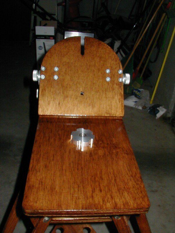
Tripod and Wedge for Criterion Dynamax SCT
Tripod and wedge for a classic Schmidt Cassegrain from the 1970's. I have an old Criterion Dynamax 8 inch SCT that I picked up through Astromart.
One of the problems with the Dynamax 8 is that it did not come with a tripod. Instead, it had two tiny legs that allowed you to set it up on a table top.
I had started making a tripod many years ago (~ 30 years) for another telescope project that I never got back to. The tripod legs and head have been around
gathering dust so I decided to finish off the tripod and add a wedge. One of the more complex parts that I have made so far for this project is the threaded rod that connects the tripod and wedge.
The rod is threaded on both ends and does not have any threads where it passes through the tripod head. As you can see from the photos it has an aluminum plate screwed
to the base of the longer thread. This plate allows attachment to the bottom of the tripod head with wood screws. The threads were cut on my metal lathe and then
finished off (deburred) with a hand die. The wedge that will hold the telescope can be seen on the bench behind the tripod in the first photo.

The Tripod

Wedge and Spreader Bolt

Wedge and Spreader Bolt
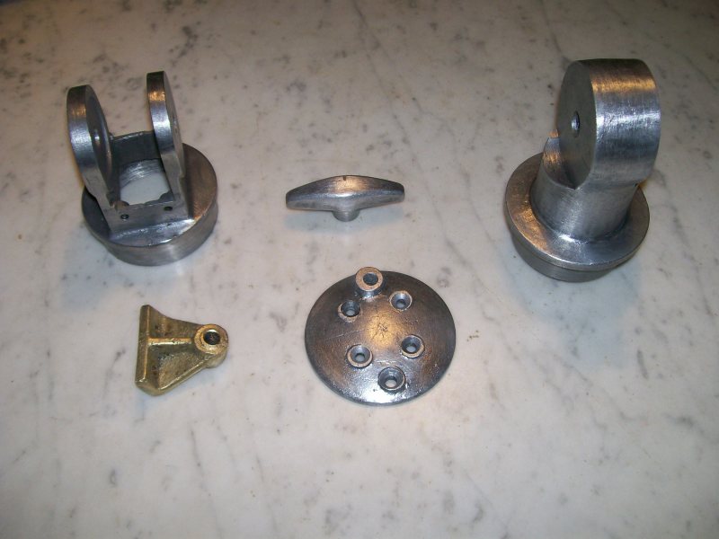
The making of the hand nuts to hold the wedge and leg locker to the tripod. On the left is a finished nut. In the center is the threaded hub for one of the nuts.
Notice that the outside of the hub is knurled so that when it is pressed into the aluminum disk it is locked in place. On the right is the setup on the milling
machine for cutting the notches in the aluminum disk.

Hand Nut

Knurled Insert

Milling Machine Setup
Here is the finished wedge. You can see that the latitude adjustments are made using locking screws and a pair of sliders. In the center
image you can see the piano hinge that attaches the two plywood plates which make up the wedge. The plywood is 3/4 inch hardwood.

Wedge

Wedge

Latitude Angle Adjustment
On the left you can see how the aluminum blocks, which are part of the latitude adjusters are held in place with four 1/4 inch screws.
In the center you can see the leg locker and the other hand nut that holds it in place. On the right is a view of the wedge and tripod.
Bolts Holding Latitude Adjustment Blocks

Leg Locker

The Tripod and Wedge
Here is the Dynamax 8 on the tripod. I immediately noticed that the wedge will need some supports on the underside to take up vibrations. The last two
pictures show the telescope on the modified wedge after the supporting frame was added. Some of the vibrations were reduced but it looks like the tripod legs need some additional work.

Scope and Tripod

Scope and Tripod

Scope and Tripod
Here is the support frame for the wedge that should take up much of the vibrations in the plywood. The plywood was much more flexible than I anticipated. The frame is made of one inch wide by 1/2 inch thick aircraft aluminum. The aluminum stock was cut to length and then the pieces were clamped together using picture frame clamps. While it was clamped together I drilled and pinned the pieces together in order to braze the aluminum together using special aluminum brazing rods. The ends of the pieces were beveled before brazing and carefully cleaned. A Mapp gas touch provided sufficient heat to bring the joints up to the 732 F temperature needed for the brazing rods. I initially tried a standard propane torch but it wasn't hot enough.

Side view of the frame

One of the brazed joints

End view of the frame

Another end view of the frame
Objective Prism Spectrograph
Objective Prism Spectrograph designed to mount piggyback on my Meade 8" SCT. It can be used with my 35 mm OM1 or the Sac7 CCD camera. The last two pictures are tests of the setup using the OM1 and Polaroid 800 ASA film with the Pleiades cluster (left) and the sword region of Orion (right). Notice in the Orion spectrum the nebular emission lines from M42.

Side View
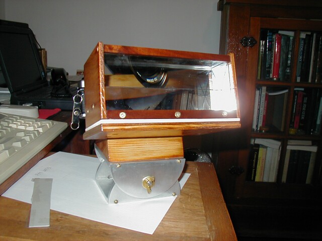
Front View
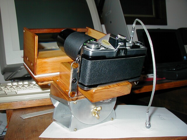
Back View

Sample Spectrum

Sample Spectrum
35 MM Camera Lens Adapter
Camera adapter that allows me to attach my Sac7 CCD camera to a 35 mm camera lens. The first picture shows one of the pieces being machined out of some aluminum scrap material. The last image shows the adapter being fitted to the Sac7 camera, 90 mm lens and objective prism spectrograph.

Machining the Bottom Half

T-Thread End

Olympus Camera Lens Bracket

Side View

Bottom View

Adapter with Lens and SAC7 Camera
Stereo Viewer Card Holder
Stereo viewer holder that I made to replace the lost holder from an antique stereo viewer that I purchased. I made it from walnut and brass. The spring-loaded piece on the bottom of the holder was made from sheet brass and the attached knob was turned on my watchmaker's lathe. The stereo card holders attached to the top were made from brass rods that were bent to shape and then fitted into holes in the walnut.

Bottom View

Side View

Top View

Holder installed on Viewer
Clock Hands
Clock hands that I made a number of years ago using a jeweler's saw. I laid out the pattern on a sheet of steel and then used the saw to cut out the hands and then filed the edges smooth. I gave the surfaces a brushed finish and then heat-treated them to give the hands a blue finish.

Clock Hands
Chauncey Jerome Ogee 30 Hour Clock Restoration
Here is a Chauncey Jerome Ogee 30 hour clock from the 1840s that I restored about thirty years ago. I purchased it for five dollars from a friend who had picked it up on one of his "picking" trips in Western Kansas. What I received for that five dollars was a case that had none of its original finish, some of the veneer along the outside edge of the front was missing in places and over one half of the veneer and underlying wood was missing from the right hand upper side of the front edge of the case. The door was missing both glass panels and the dial only had about one quarter of its original paint. The case had about one hundred years of mud dauber nests both on the inside and the outside of the case. About one third of the paper label on the inside of the case was missing. The weights were still present and the movement looked to be in good shape. The hands were also still present, but the pendulum bob was missing. At the time I did not think of photographing the original condition of the clock. I am very sorry now that I did not do that.
At first I planned to discard the case due to its horrible condition but then I decided to use it as a chance to learn how to do a full restoration. The first order of business was to remove the dial and movement and then remove all of the mud dauber nests and then to give the case a careful cleaning. Once that was done I carefully removed the remnants of the 7/8 inch trim and veneer from the right hand side of the case's front and fabricated a new piece of wood trim and glued that into place and added new veneer to it. The few inches of veneer from that piece of trim that I removed was used to patch the missing veneer on the rest of the outside trim of the front of the case.
After lightly sanding the case I re-stained and varnished (real varnish, no polyurethane) the case. I used lightly diluted varnish and applied several thin coats so that I had a nice even streak free finish.
The label on the inside of the case was loose so I used diluted Elmer's glue (50% glue/50% water) with a syringe and injected the glue under the label.
I did a complete rebuild of the movement, installing new bushings and polishing all of the pivots, replacing the lantern pinion wires and reground the verge surfaces. I was able to find an antique pendulum bob, replaced the suspension spring, and replaced the strings on the time and strike main wheels.
The dial was restored by a professional dial restoration expert. At that time the dial restoration cost me $100 US dollars, which was the most expensive part of the restoration. She did a wonderful job simulating age cracks and wear around the winding holes.
The upper glass in the door came from an antique picture frame and the reverse painted glass panel was picked up at a clock and watch show in Nebraska. The reverse painted glass fit perfectly into the door like it was made for that door. That reverse painted panel was the second most expensive part of the restoration, costing me $35 US dollars at the time.
Overall I spent about $150 US dollars restoring the clock, which is more than it is worth but it was a good learning experience.

Chauncey Jerome Ogee 30 Hour Clock

Chauncey Jerome Ogee 30 Hour Clock Showing Replaced Section of Case