
Chautauqua Courses
Interferometry in Radio Astronomy: The VLA and VLBA
Held in Socorro, New Mexico on July 11 through Jul7 13, 2007 at the NRAO Headquarters
VLBA Operations Center
The image on the left shows South Baldy Peak (10,783 feet), which is to the west of Socorro. The local golf course is in the foreground. The image on the right shows the observatory operations center in Socorro where the VLBA (Very Large Baseline Array) is managed.

South Baldy Peak.
VLBA operations center.
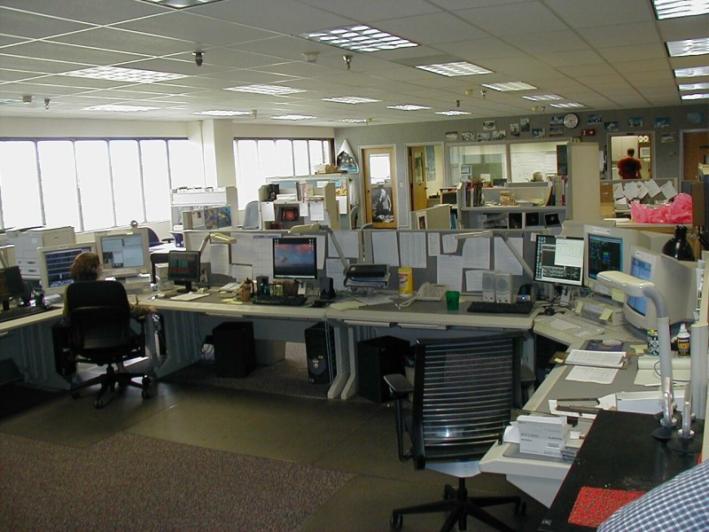
NRAO Daily Staff Meeting
Wednesday noon NRAO staff meeting where staff members discussed eMerlin, an interferometer being built in the UK, in cooperation with NRAO. They discussed how budget shortfalls were impairing the project, laying of optical fibers between radio dishes, above ground along rail lines (perhaps not a good idea), artificial deadlines, and how one poor programmer was going to rewrite all of the antenna control software. Sounds similar to what I face in the corporate world.

The staff meeting.

The presentation on the progress of eMerlin
ALMA Electronics
The project manager for the ALMA (Atacama Large Millimeter Array) electronics explains the workings of the analog to digital converter units that will be fitted into the base of each of the ALMA dishes in Chili. At the time that I took this class the ALMA array was just beginning construction and they had several of the ALMA dishes being tested on site and they were building the electronics for the dishes.

Project manager in front of ALMA analog to digital converter.

One of the analog to digital converters.
The VLBA Correlator
The correlator combines the signals from the different dishes on the array to make a single image. The correlator is basically a super computer made up of individual processors (correlator boards) working in parallel.

One of the VLBA correlator cabinets.

A VLBA correlator board.
The Raw Data
Data from different sites around the world is shipped to the VLA facilities on disk packs (arrays of hard drives that store the data in a redundant manner) where they are read into the systems. In the old days they used VCR tapes to store the raw data and banks of VCR players to read the data.

Disk packs for the VLBA sitting on shelves.

Disk packs for the VLBA being read.
The Electronics Lab
The image on the left shows the VLA test racks where repaired components are tested prior to installing out at the array. The image on the right shows a cross section of one of the wave guides used to transmit data from the antennas to the main building where the signals are processed. These wave guides are being replaced with fiber optic cables as part of the upgrade that will boost the array's sensitivity.

The test racks.

Wave guide.
The image on the left shows a feed horn electronics in the process of being tested. The insulated lines going into and out of the assembly are helium lines, which are used to cool the electronics. The electronics are housed in the aluminum chamber, which is evacuated to prevent condensation. The image on the right shows aa couple of repaired receivers. Note the feed horns and the vacuum chambers. The electronics in the receivers are cooled with helium gas and kept in a vacuum to reduce noise. The vacuum is necessary to prevent condensation.

Feed horn electronics being tested.

A couple of repaired receivers.
On the left is one of the receiver electronics packages that sets behind a feed horn showing the components that split the signal into right and left circularly polarized signals. On the right is the same unit with the piece that holds the feed horn and channels the signal to the electronics via millimeter sized wave guides.

Receiver electronics package.

Assembly that channels the signal.
The VLA Radio Dishes
The image on the left shows me in front of the antenna hanger. When an antenna is brought to the hanger the dish is removed from the base if the azimuth bearing shows excessive wear and a new bearing can be installed. This dish was being retrofitted for an upgrade to the array. The image on the right shows one of the antennas of the array in for repairs next to the antenna hanger. This dish was just refitted as part of an upgrade project to boost the array sensitivity.

Me in front of the antenna hanger

Antenna in for repairs.
On the left is Dave Finley, who was our guide throughout the class, explaining some of the features of the radio dish before taking our class up onto the antenna. The image on the right shows us on the surface of the dish listening to Dave Finley explain about the workings of the dish surface and the secondary reflector.

Preparing to go onto the dish.

On the dish surface.
At the base of each radio dish is a room that hold the feed horns and electronics.

Inside the antenna looking up at the feed horns.

The feed horns.
Each of the dishes on the array is connected by fiber optics. The image on the left shows the fiber optics connections in the electronics room at the base of the dish. The image on the right shows us preparing to climb through the hatch in the dish.

The fiber-optics inside the dish.

Climbing out onto the surface of the dish.
The image on the left shows the five horsepower motors that move each of the dishes in altitude. The iamge on the right shows the adjustment bolts that are used to fine tune the parabolic shape of the dish.

The five horsepower motors.

The adjustment bolts.
The image on the left shows the secondary reflector dish that reflects the signals from the main dish to the feed horns. The image on the right shows the feed horns as seen from the dish.

The secondary reflector dish.

The feed horns.
The VLA Antenna Transporters
The VLA can change the configuration of the array by moving the antennas to different positions along the Y shaped tracks. To move the antennas (dishes) they use transporters that lift up the antennas and move them to new positions. One of the antenna transporters is pictured on the left. When they move an antenna they have to insert track splices to move the antenna from the pad to the main track. The picture on the right shows one of the track splices used when a dish is moved from one of the stations onto the main track. The antenna transporter uses hydraulic jacks to lift itself off the track and then rotates the wheels onto the main track.

Antenna transporter.

Track splice.
The image on the left show the wheel assemblies of the antenna transporter. The image on the right shows a close-up of the rotary hydraulic motor on one of the wheel assemblies.

Wheel assemblies.

Rotary hydraulic motor.
The VLA Operations Center
The image on the left shows the antenna control room at the VLA. The image on the right shows a view of the computer control screens. Notice the UNIX for Dummies book on the desk. Seeing that makes me feel a bit better about having to look up UNIX commands.

Control room.

Computer control screens.
VLA Analog to Digital Converters
The image on the left shows one row of analog to digital converters for one branch of the array. There are nine converters in each row (one for each of the nine dishes that makes up a branch). The image on the right shows the fiber-optic cables going to the correlators.

Analog to digital converters.

Fiber-optic cables.
ALMA Prototype Dishes
The image on the left shows two of the prototype ALMA antennas for the new sub-millimeter array being built in the Atacama desert of Chili. The image on the right shows the two ALMA dishes seen from behind.

Front view.

Rear view.
Some Miscellaneous Images
The image on the left shows backup tapes of the all of the processed data collected at the VLA from 1976 to present. The image on the right shows a pronghorn antelope walking through the observatory grounds.

Backup tapes.

Pronghorn antelope.
Eagle Guest Ranch
We completed our trip to the VLA by having lunch at the Eagle Guest Ranch in Datil New Mexico. The image on the left shows us having lunch The image on the right shows us listening to Dave Finley tell stories about the filming of the movie "Contact" over lunch.

Lunch

Hearing about the filming of "Contact".
Panoramas
The following panoramas were created with Autostich, which is available from the author's (Matthew Brown) home page. Autostich Home Page
Panorama from the balcony of Baca Hall where we stayed. Full sized image. 1,613Kb

Panorama of the VLA showing the operations center, the two ALMA prototype dishes, and one leg of the array. This image was taken from the antenna hanger. Full sized image. 1,151Kb

Panorama of the VLA taken from the operations center. Full sized image. 1,915Kb

New Mexico Tech University Mineral Museum.
We visted this during our lunch break on Wednesday.

Example of gold mined in New Mexico.

More gold from New Mexico.

Minerals from the southwestern states.

Calcite crystals from California.

Native copper from New Mexico.

Cuprite from New Mexico.

Gypsum crystal from Socorro County New Mexico.

Barite from New Mexico.

Ultraviolet display showing fluorescent minerals.

More fluorescent minerals.
A Radio View of the Universe and the New Green Bank Telescope
Held in Green Bank, West Virginia on May 30 through June 1, 2006
The Reber antenna at the entrance of the observatory. Reber was the first radio astronomer. He built this dish in his backyard during the 1930's and listened to radio emissions with head phones and recorded his observations in a notebook. The alt-azimuth design is basically the same as the giant 100 meter radio telescope.

Reber antenna.
The first 21-cm horn on display next to the observatory lab building. Made from wood and sheet metal.

First 21-cm horn.
The Drake equation. The small conference room in the astronomer quarters where we stayed had this plaque hanging over the fireplace. The Drake equation, which attempts to quantitatively estimate the number of advanced civilizations in our Milky Way Galaxy, was first proposed in this conference room.

The Drake equation.
The 40 foot radio telescope used by our class. This telescope was the first to be used in the SETI program. It is now used for educational purposes. Its electronics were salvaged from the old 300 foot telescope that collapsed into a pile of twisted scrap metal in November 1988.


At the controls of the 40 foot radio telescope. Three members of our class (Bill, Steve and John) learn to take 21-cm spectra of the Milky Way.


The 45 foot radio telescope used for solar flare observations. Apparently, sunspots make a lot of radio noise before flares explode. This telescope tracks the Sun every day watching for possible flares.


Early morning views of the observatory. In the center of the left picture is one of the dishes of the interferometer. In the distance on the are the 140 foot radio telescope and the 100 meter telescope. On the right is the US Navy radio telescope that was used for GPS work. Currently this radio telescope is idle.

On the left is another view of the US Navy radio telescope. On the right are two more of the dishes that make up the interferometer as seen from the top of the 100 meter radio telescope.


The 100 meter Robert C. Byrd radio telescope. This telescope is also simply known as the GBT. This telescope is the replacement for the 300 foot telescope that collapsed in 1988. Senator Byrd obtained the 100 million dollars for its construction from federal emergency funds. He called the 300 foot collapse a "great catastrophe".


On the left is the elevator that took us up to the altitude bearings. From there we walked the cat walk to the elevator that took us up the receiver arm to to feed room. On the right is the platform at the level of the altitude bearings.


On the left is another view from the altitude bearing platform. In the center is the head astronomer over the GBT pointing out the various features of the telescope. On the right is a view of the panels and actuators that make up the dish. There are over 2000 panels and the actuators are able to adjust the shape of the dish to within a fraction of a millimeter.


On the left is a view from the top of the feed horn room showing the openings of the various feed horns. The large feed horn in the foreground is the 21-cm horn. The image on the right shows the 10 meter secondary dish and the primary focus feed.


Inside the GBT feed room. Top row: the 21-cm detector. Bottom row: some of the other detectors. These detectors are cooled to 15 Kelvin with helium gas that is cooled through a multistage expansion process. The helium makes a loud chirping sound as it passes through the plumbing.


Two views of the azimuth wheels that support the GBT. There are 16 wheels that support 1 million pounds each. While we were climbing the GBT, maintenance workers were replacing sections of the circular track. The track is covered by a sheet metal cover to prevent objects from falling under the wheels. The image on the right shows two of the workers taking a break beside the wheels. The sheet metal cover can be seen in the left hand image.


Two animation sequences showing the GBT in operation. Animations are provided by the NRAO.